
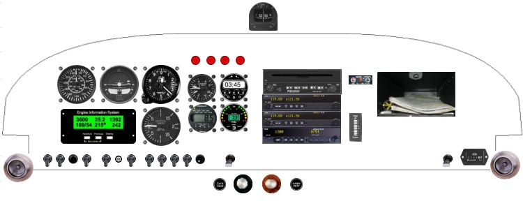
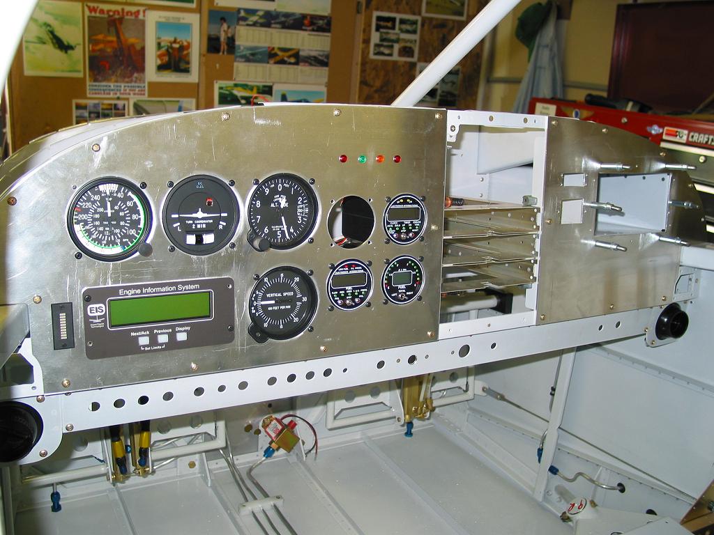
Here's the current designed panel layout.
| Here's the basic instrument panel blank mostly cut out and being fit into the fuselage. The cuts still need to be refined and other mounting supports added. More to come! | 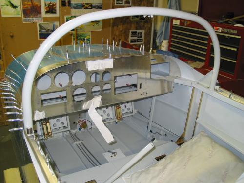 |
| Well, after thinking through my current setup. Not to
mention the fact that I made a few mistakes during the cutting of the
stock panel... and lastly the new option of a cool new panel technology
coming on the market. I have decided to replace the stock panel as seen
above with a new panel from Affordable
Panels.
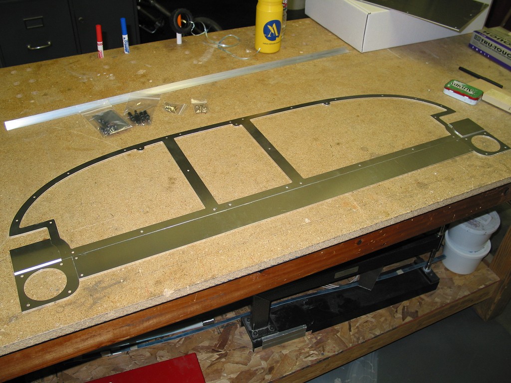
This is a cool setup with a sub frame that matches the existing structure. Then the actual panel bolts onto the sub frame in 3 sections. This allows the panel to be selectively removed for access to the instruments behind. This is going to make future upgrades and maintenance a breeze! The other really neat feature is that the panel will have an additional switch mounting location below the main panel sections. Have the switch sub panel will allow the panel to come out easily and leave the switches permanently wired into the structure. All this and a cool computer cut sub frame and panel sections. Check back soon for more updates and pictures of the new panel installation. |
|
 |
 |
 |
 |
 |
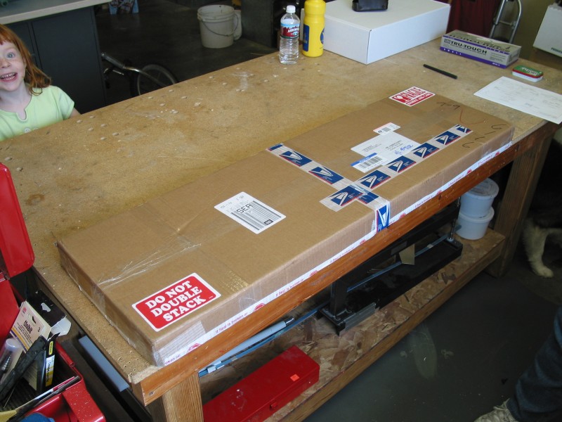
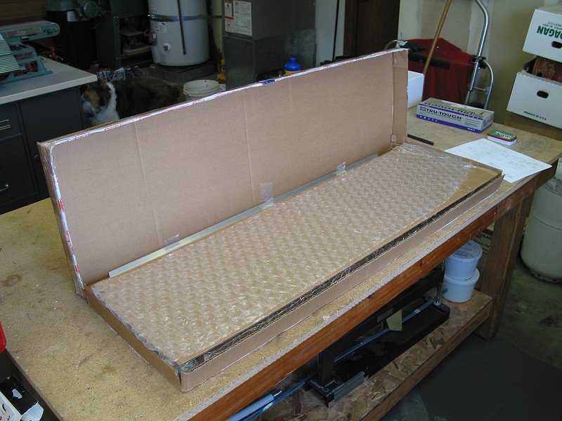
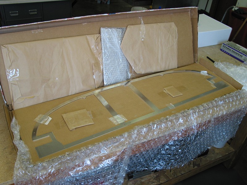
Well here's the new panel from Affordable Panels. It came very quickly.
2 days I think. Was packaged nicely and securely and arrived without any damage
at all. Upon opening the box you know you have a precision part in your
hands. This thing is finished very nicely and will only require basic
deburring before priming.
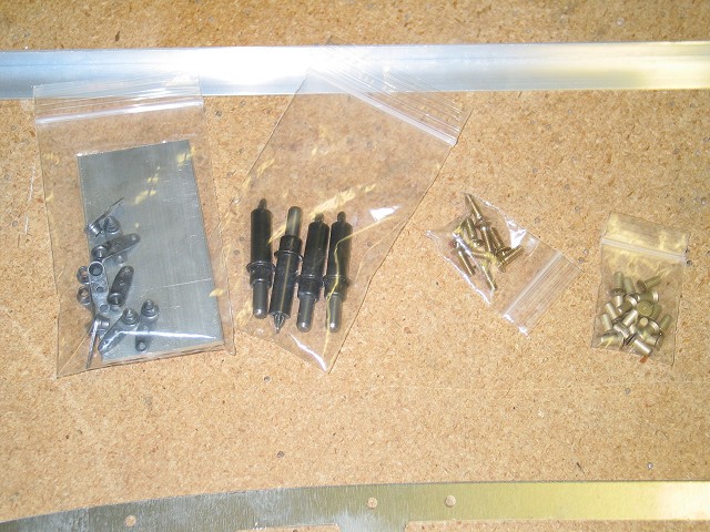
The included hardware is pictured at the left. 5/32 rivets! WOW those are big. They replace the nutplates and screws of the original panel attach to the skin stiffeners. A very nice touch is the inclusion of 4 large size 5/32 cleco's. I didn't have any of these and they sure make working with #8 screw holes nice! |
 |
 |
 |
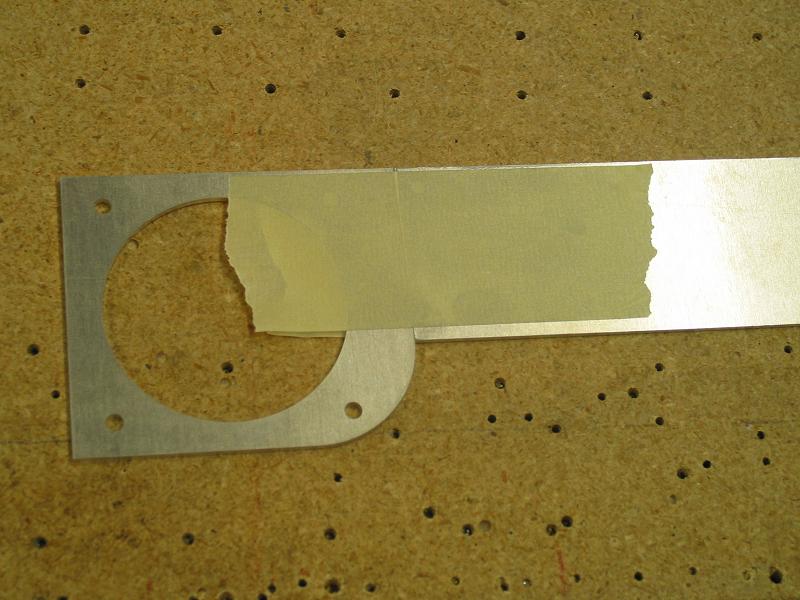
The first step is to match everything up with the old panel and drill
the mounting hole using it as a template. One of the cost savings is that
you can send back the original panel, however I was too far along and have
already hacked up the original panel. Possibly I could offer it back to
Van as a new prepunched model? Doubtful...
|
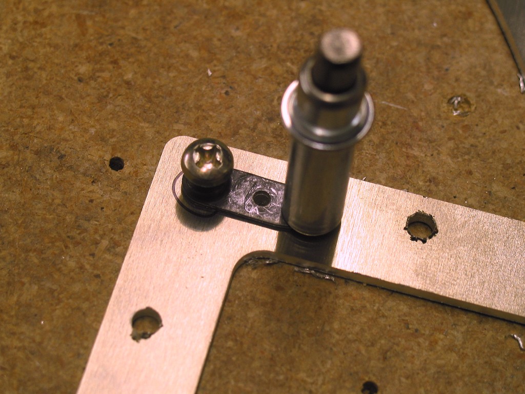
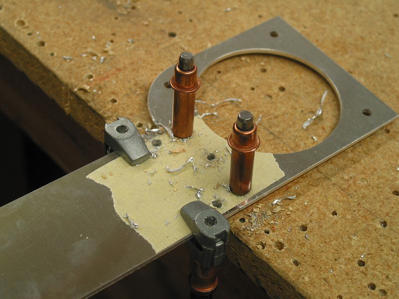
| Here is my favorite method of locating & drilling platenuts to the
holes. Take a platenut (either standard or these single leg ones) and take
a 8-32 tap through them. Once they are opened up a bit you can put a #8
screw through them backwards. Then using the #19 holes that you drilled
through the part and the table slip the end of the screw into the hole and
drill the mounting holes into the frame.
This has worked great all over the plane thus far and didn't cost anything! |
 |
 |
 |
 |
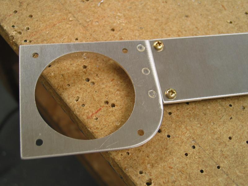 |
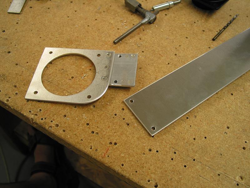
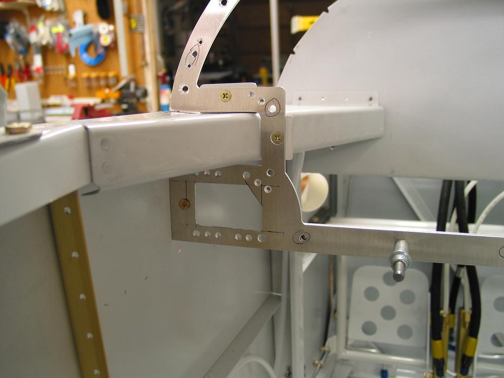
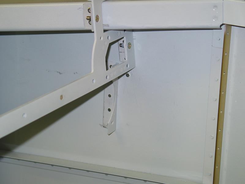
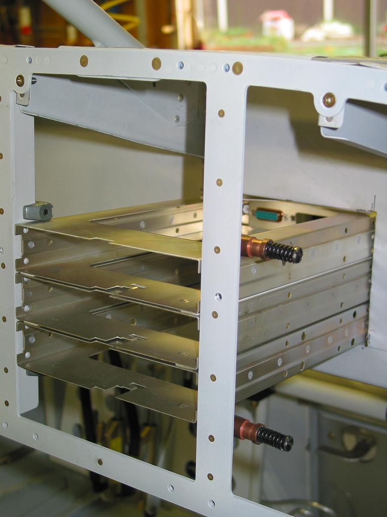
| Above you can see some of the vent and switch panel parts as they are
fabricated and mounted together.
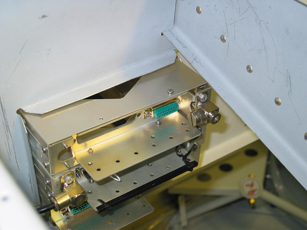
At right is the main sub-frame being installed in the fuselage. It fit perfectly where the stock Vans panel used to be. Below you can see the new support bracket riveted to the sidewalls to support the air vents in their new location next to the switch panel. |
 |
 |
 |
 |
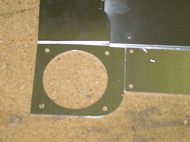
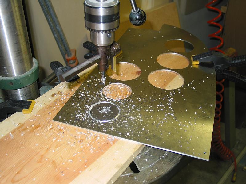
Nothing fancy here, just using a fly cutter to mash out the circles for
the instruments to mount in. I got a basic stamped out steel template from
the tool vendors to drill the instrument mounting screw holes. It worked
great.
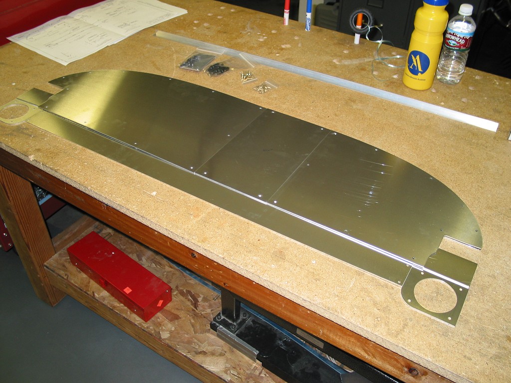
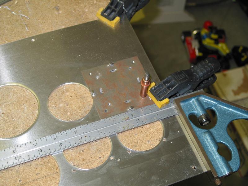
One of the really cool things about the modular panel is that you always have 1 or more straight sides to align everything off of. I used the square extensively to always make sure that what ever hole or location I was working with was square to the panel blank. |
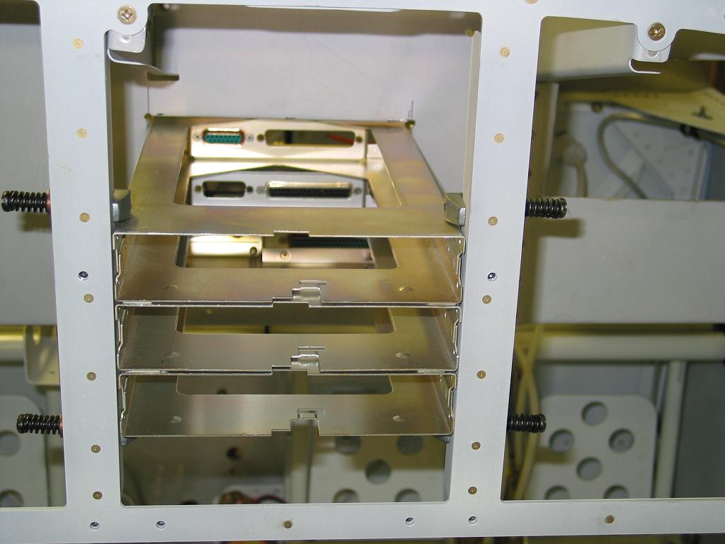
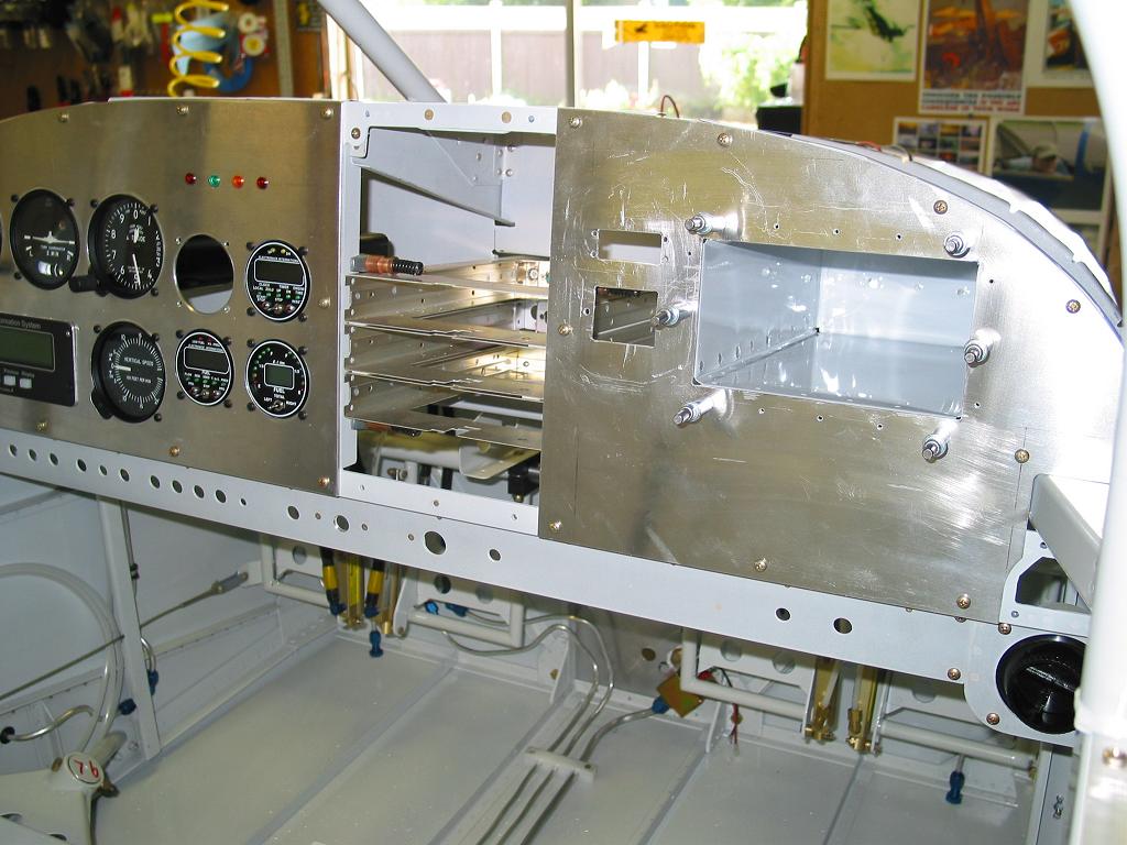
| Here is the finished main sub panel with all supports riveted on and installed. The radio trays are set in right now and read to be drilled and bolted in place. The sub panel cutout from the previous panel installation worked out perfectly and everything slid in to place nicely. | 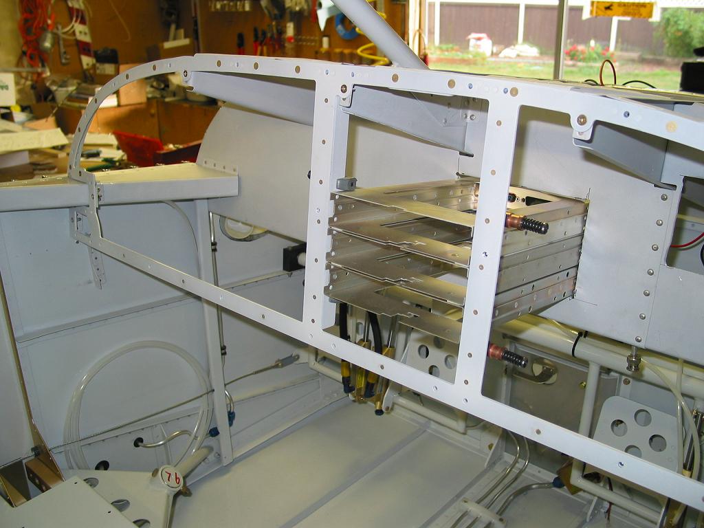 |
 |
 |
 |
 |
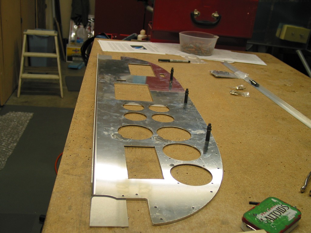
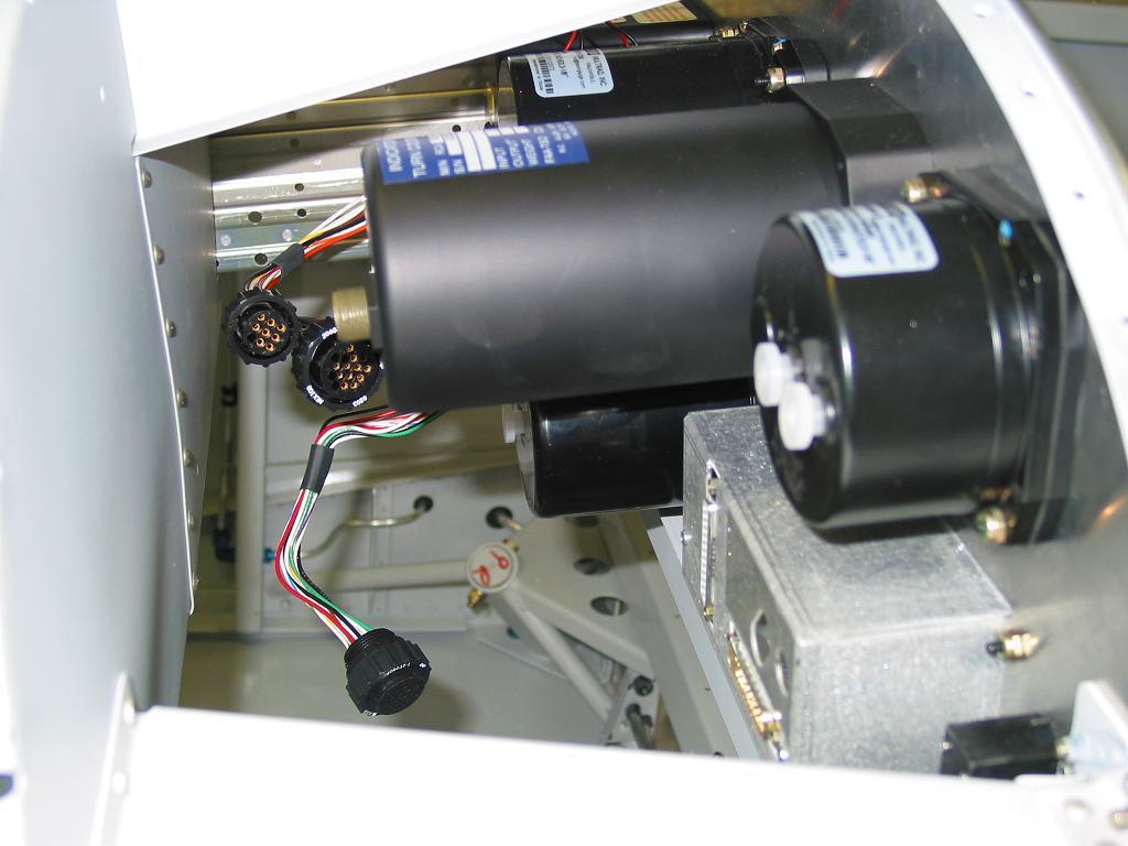
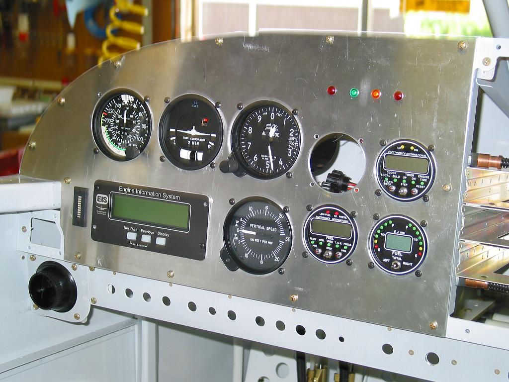
Next step was the installation of all the instruments to ensure that everything fit properly. (As always, click to enlarge)
 |
 |
 |
 |
Then the final step is to paint and install everything for good... Stay tuned...